
1 Jan 3 2016 - I finished building the steel bracket that supports the middle level benchwork where the mainline nolix crosses over the aisle as it heads up to the upper level. I have also started cutting and dry placing the 3/4" plywood subroadbed for the lower return loop and staging tracks that will be hidden under the city (Ogden). Once I am happy with the layout of subroadbed before screwing it down I will use it as templates to cut 1/2 homasote roadbed. This task has also forced me to figure out exactly how I am going to support the plywood base of the city above the hidden return loop (as well as how the detachable backdrop behind the 42" deep high rise city scene will be built/installed.

2 This benchwork projects 48" from the wall and the top of the 1x3 benchwork is 77.5" elevation.

3

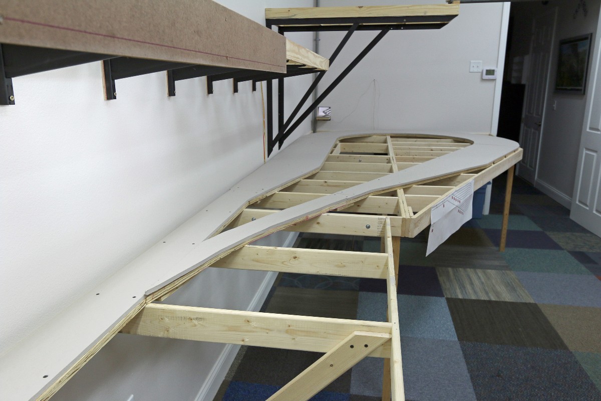
4 Working on laying out the subroadbed for the double track mainline as it climbs a 1.3% grade and emerges from under the city.

5 I finished installing the layout lighting LED strips that light the lower level. Note the "start climb" notation on the left. This is the point where the middle level nolix starts the 2.0% climb up to the upper level.

6 Placed the board that shows the span where the mainline crosses the aisle on its way up to the upper level.
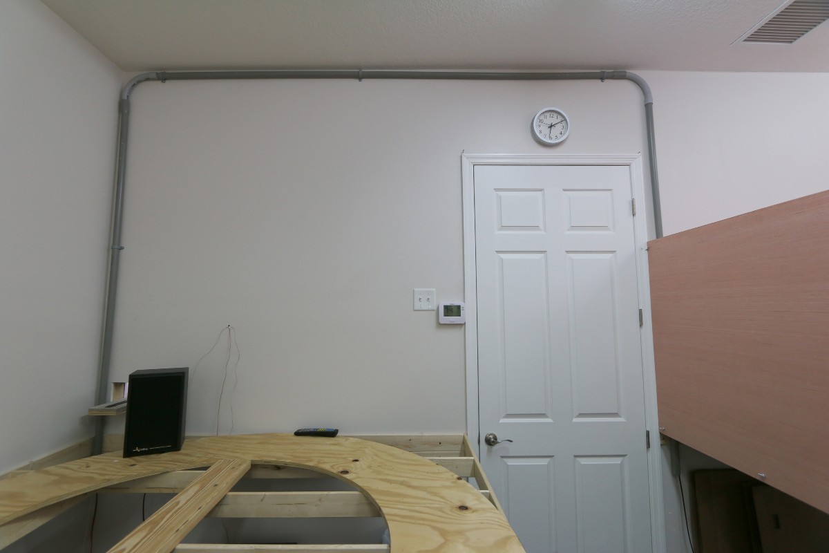
7 I also installed a conduit over the door to allow me a shorter run for electrical cables/busses as an alternative to going all the way around the outside of the room. I considered trying to run the conduit inside the wall but this wall is a load bearing wall (with lots of extra blocking), it has all the plumbing for the bathroom, and it has a bunch of electrical. So I took the ugly path of less resistance.

8

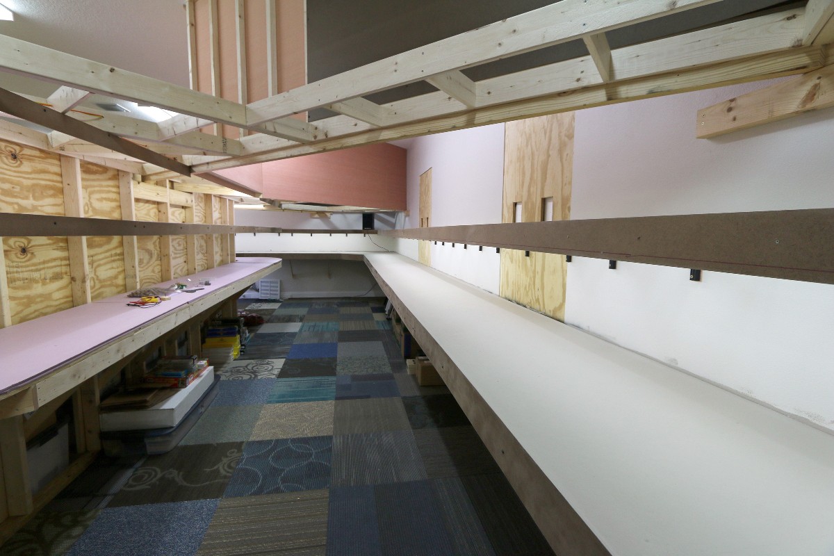
9 Showing the newly installed LED layout lighting sections with the room lights turned off.

10

11

12 The lower return loop double track mainline will exit a tunnel portal at the bottom left of this photo. You can see where it will transition from the homasote roadbed to the Woodland Scenics 3/16" foam roadbed about 3 feet from the exit of the tunnel.

13 I created a 1:1 scale design proposal for a control panel for the hidden lower return loop and staging track. The red squares represent momentary switches that will toggle the turnout position. The green circles represent 5mm bicolor LEDs that will indicate the turnout status (closed/thrown). The red circles represent 5mm LEDs that indicate occupancy zones. It also shows where the track is gapped. The control panel would mount about 7" above it's current location once the plywood/foam base for the city is installed.
14

15 Jan 10 2015 - I painted/sealed the homasote subroadbed for the lower return loop. The color is Behr N200-3 "Nightingale Gray". In the top left corner you can see a train crossing the aisle on the "plate girder" bridge that will be used to cross above the aisle into the upper level.

16 The 8 ft long "U" channel raw steel bar that I plan to use to cross aisle into the upper level was delivered last week. It is 3" wide and 1.5" tall. I plan to glue a section of 1/2" homasote into the U channel to use as roadbed. This allows the train to be clearly visible as it crosses approx 80" above the floor but still (hopefully) provides some ability to "catch" wayward trains before they make to death fall to the floor. I need to get the raw steel sanded and painted soon to avoid it rusting (of course some rust might be appropriate as 'weathering').
17 I used caulk to cover the drywall screws and seams in the homasote roadbed of the yard area. After caulking I painted it with the Behr Nightingale Gray to seal it.

18 The loco service area in the lower right

19

20 I finally started laying track (In the lower return loop). The track is Atlas code 100.


2016