
1 This is overall design of the layout. It's a three level mushroom design.The lower and middle levels are viewed from the aisles and the upper level is viewed from inside the center platform. The floor of the center platform is 30" above the room floor. The overall design of the layout is a 'loop to loop' with a long mainline run between the end loops. The lower return loop is in the top right corner and will be hidden under the large city. The upper return loop is above the helix next to the center platform. There is about 500 ft of mainline run between the lower and upper return loops.

2 The lower level. Most of the lower level is at 42" elevation. My freelance version of the city of Ogden Utah is located along the top/right of the lower level. In my freelance version of Utah in the 1950s, Pirates from the Great Salt Lake founded Ogden. ;)

3 The mainline exits the helix at 62" elevation on the middle level. About half the middle level is flat at 62" but then it starts climbing (2% helper district) until reachs about 80" where it crosses above the aisle into the upper level.

4 The upper level mainline track starts at about 80" elevation and levels out at 82" elevation. With the 30" high raised floor of the center platform it is effectively 52" high. The mainline enters a tunnel before reaching the upper return loop (with 5 staging tracks) which is above the helix. There is a branchline that splits off the mainline and climbs up to 88" (58" relative) to service a large industry (or town) above the upper return loop and helix).

5 Lowes delivered the initial load of lumber for the layout benchwork.

6 First I built a storage rack for the lumber....

7 .
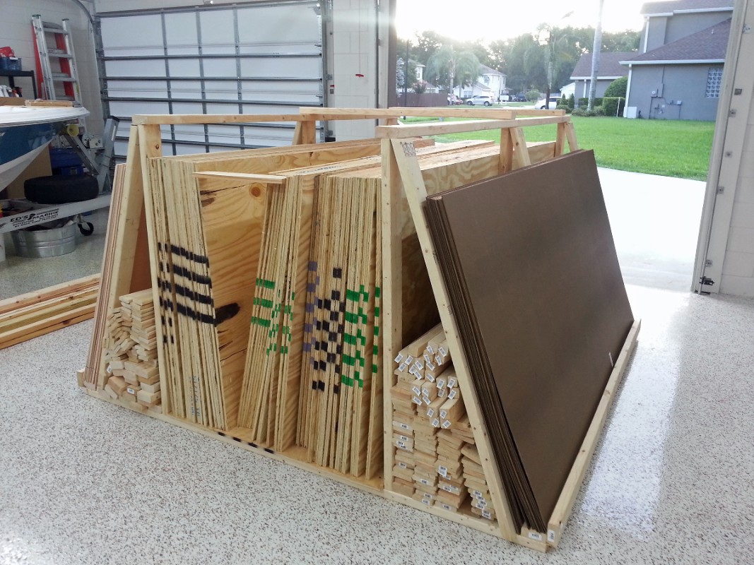
8 Finally I moved all the lumber from the driveway into the garage.

9 .

10 This is a 3D overview with the backdrops and terrain removed. The pink areas will be 1" rigid foam sheets.

11 Simplified bus wiring diagram

12 .

13 This is what the train room looked like before construction on the layout started.

14 And then I started on building the 'center platform'.which makes the 'room within a room' of the mushroom layout design.

15 The benchwork leaning against the wall in the background was recovered when I deconstructed my old layout. I may be able to use some of it in the new layout,otherwise I will take the pieces apart and reuse the 1x4 and 1x3 boards.

16 Building floor joists to support the 30" high floor of the center platform.

17 You can see the 2" rigid foam insulation in the windows on the back wall.

18

19 Wide angle perspective showing the size of the center platform.

20 The joists were spaced 24" on center so I can use the area under the center platform to store the large plastic storage tubs.


2015